A utility network is the main component users work with when managing utility and telecom networks in ArcGIS, providing a comprehensive framework of functionality for the modeling of utility systems such as electric, gas, water, storm water, wastewater, and telecommunications. It is designed to model all of the components that make up your system—such as wires, pipes, valves, zones, devices, and circuits—and allows you to build real-world behavior into the network features you model.
After you prepare a utility network in ArcGIS Pro, you can deploy it to Field Maps, where mobile workers can view associations within the network and perform traces. Field Maps supports the following utility networks: electric, gas, water, storm water, and wastewater.
Caution:
Editing the utility network is not currently supported in Field Maps.
Viewing and editing maps containing utility networks is not supported in Map Viewer.
Note:
Viewing associations is supported in ArcGIS Enterprise 10.8 and later. Named trace configurations are supported in ArcGIS Enterprise 10.9 and later. Utility networks are not currently supported in ArcGIS Online.
Utility networks in Field Maps are supported for online, read-only workflows. Offline and editing workflows are not currently supported.
Prepare the utility network
Utility networks are created and configured using ArcGIS Pro. Before deploying a utility network to Field Maps, learn how to get started with utility networks and consider the following:
- Requirements—Review the requirements and prerequisites for configuring utility networks in ArcGIS Pro.
- Display filters—Optionally, set up display filters to control which features display on the map.
- Subtype group layers—Optionally, configure subtype group layers to symbolize and display individual subtypes on the map.
- Named trace configurations—Optionally, set up named trace configurations so mobile workers can trace networks.
Once you've configured the utility network, publish and share it with mobile workers so they can access it in Field Maps.
Get started with utility networks
To create utility networks for use in Field Maps, you must use ArcGIS Pro. See the following resources to get started:
- Getting started with the ArcGIS Utility Network
- What is a utility network?
- Utility network creation and configuration
Once you've created a utility network, you can optionally set up display filters, subtype group layers, and named trace configurations before deploying it to Field Maps.
Set up display filters
Note:
To set up display filters for use in Field Maps, you must use ArcGIS Pro 2.9 or later.
Set up subtype group layers
Subtype group layers allow subtypes within a feature layer to be viewed as individual layers within the map. For example, if an electric devices layer contains 50 subtypes, each subtype can be used and symbolized as a distinct layer. This allows mobile workers the flexibility to turn individual subtypes on and off and more easily identify subtypes when working with the map in Field Maps. To learn how to set up subtype group layers in ArcGIS Pro, see Subtype group layers.
Set up named trace configurations
Named trace configurations allow you to return results based on the spatial layout and representation of equipment within the utility network—showing where resources flow from a certain point based on certain criteria. For example, if a power line is down, you can perform a downstream trace in Field Maps that displays all affected homes within a neighborhood. Named traces are configured in ArcGIS Pro and must be shared with the web map to work in Field Maps. To learn how to set up named trace configurations in ArcGIS Pro that can be used in Field Maps, see Named trace configurations.
The following trace types are supported in Field Maps: upstream, downstream, isolation, subnetwork, subnetwork controllers, connected, and loops. To learn how to perform traces in Field Maps, see Trace networks.
Note:
Named trace configurations are supported in ArcGIS Enterprise 10.9 and later and ArcGIS Pro 2.7 and later.
Publish and share the utility network
Once you've configured the utility network, publish and share it as a web map from ArcGIS Pro to your ArcGIS organization so mobile workers can access it in Field Maps.
View associations
Mobile workers can use Field Maps to view associations within a utility network, including connectivity, structural attachments, and containment.
Note:
To learn how to create and manage associations in ArcGIS Pro, see Associations. Configuring connectivity, structural attachments, and containment is supported in ArcGIS Pro 2.6 and later.
View connectivity
Connectivity models the connections between features in a utility network. Viewing connectivity is helpful when working in areas where connections between features aren't always apparent—such as in electrical substations. To view connectivity in Field Maps, complete the following steps:
- Open the map containing the utility network.
- Tap Layers
 and turn on the Connections network layer.
Red dashed lines appear between connected features. In this example, a circuit breaker, transformer bank, and terminator are shown to be connected.
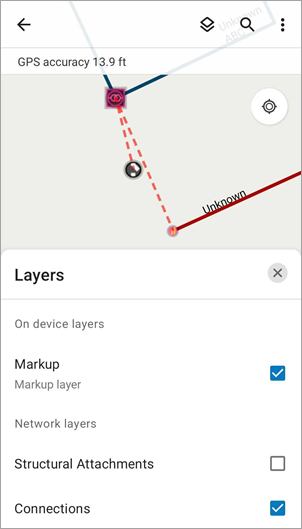
To learn how to configure connectivity in a utility network, see Connectivity associations in ArcGIS Pro.
View structural attachments
Structural attachments model associations between features in the domain network and features in the structure network. For example, a power pole contains four power lines, each its own feature layer. Structural attachments in Field Maps can display the connection between each of these feature layers connected to the same pole. This allows mobile workers to interact with each power line feature individually while understanding how they connect to one another. To view structural attachments in Field Maps, complete the following steps:
- Open the map containing the utility network.
- Tap Layers
 and turn on the Structural Attachments network layer.
Green dashed lines appear between features connected to the same structure. In this example, four power line features are shown to be connected to the same power pole.
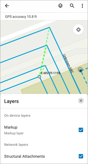
To learn how to configure structural attachments in a utility network, see Structural attachment associations in ArcGIS Pro.
View containment
Containment models the association between features and the containers they're in (such as substations or transformer banks). There can be many features within a container, some of which may not display in the map due to layer visibility settings. With containment in Field Maps, you can automatically display and select all objects within a container—ensuring all contained features are accounted for. To view containment in Field Maps, complete the following steps:
- Open the map containing the utility network.
- Tap a containment feature within the network to select it.
In this example, a substation within an electric network is selected.
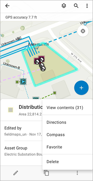
- Swipe up on the panel or tap the overflow menu, and tap View contents.
All features within the container are selected and displayed in the panel.
Note:
If you select an individual feature, you can identify the container it's associated with. After selecting the feature, tap View container and the associated container is selected.
To learn how to configure containment in a utility network, see Containment associations in ArcGIS Pro.
Trace a network
Named trace configurations allow you to return results based on the spatial layout and representation of equipment within the utility network—showing where resources flow from a certain point based on specific criteria. Named traces are configured in ArcGIS Pro and can be performed in Field Maps. For example, if a power line is down, you can perform a downstream trace that displays all affected homes within a neighborhood.
The following trace types are supported in Field Maps: upstream, downstream, isolation, subnetwork, subnetwork controllers, connected, and loops.
Field Maps supports traces from terminals, points, and lines within a network and supports selection and aggregated geometry result types. You can also set up functions to return calculations with each result type.
Note:
Named trace configurations are supported in ArcGIS Enterprise 10.9 and later.
To trace a network in Field Maps, complete the following steps:
- Open the map containing the utility network.
- Tap a terminal, point, or line within the network.
Named traces that have been configured for the utility network are shown as actions in the panel and the panel's overflow menu. In this example, there are three trace actions available for a selected power line feature—connected, downstream, and upstream.
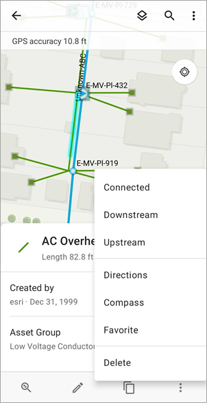
- Tap a trace action to initiate the trace.
In this example, the Downstream trace action is tapped. After selecting a point on the line to start the trace, Field Maps returns and selects the list of assets that receive electricity from the power line.
Note:
This example returns a selection of features as a result; however, you can also configure named traces to return an aggregated geometry. See Result types in ArcGIS Pro to learn more.
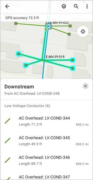
Additionally, you can configure function results to return calculations with traces. For example, you can configure a function that returns the number of homes affected or the total voltage included in a downstream trace. To learn more about configuring function results, see Set up functions in ArcGIS Pro.
To learn about other types of traces that can be performed in Field Maps, see the list of supported trace types above.